| 15 | 0 | |||||||||||||||
| x3000 | 0 | 0 | 1 | 0 | 0 | 0 | 0 | 0 | 0 | 0 | 0 | 0 | 0 | 1 | 0 | 0 |
| x3001 | 0 | 0 | 0 | 1 | 0 | 0 | 0 | 0 | 0 | 0 | 1 | 0 | 0 | 0 | 0 | 1 |
| x3002 | 1 | 0 | 1 | 1 | 0 | 0 | 0 | 0 | 0 | 0 | 0 | 0 | 0 | 0 | 1 | 1 |
| x3003 | 1 | 1 | 1 | 1 | 0 | 0 | 0 | 0 | 0 | 0 | 1 | 0 | 0 | 0 | 0 | 1 |
| x3004 | 1 | 1 | 1 | 1 | 0 | 0 | 0 | 0 | 0 | 0 | 1 | 0 | 0 | 1 | 0 | 1 |
| x3005 | 0 | 0 | 0 | 0 | 0 | 0 | 0 | 0 | 0 | 0 | 1 | 1 | 0 | 0 | 0 | 0 |
| x3006 | 0 | 1 | 0 | 0 | 0 | 0 | 0 | 0 | 0 | 0 | 0 | 0 | 0 | 0 | 0 | 1 |
The PC contains the value x3000, and the RUN button is pushed.
As the program executes, we keep track of all values loaded into the MAR. Such a record is often referred to as an address trace. It is shown below.
x3000
x3005
x3001
x3002
x3006
x4001
x3003
x0021
How many
TRAPservice routines can be implemented in the LC-3? Why?Why must a
RETinstruction be used to return from aTRAProutine? Why won't aBRnzp(unconditionalBR) instruction work instead?How many accesses to memory are made during the processing of a
TRAPinstruction?
a. 256 TRAP service routines can be implemented. x0000- x00FF
b. RET stores the value of PC (before execution of the service routine) in R7 so that it can return control to the original program after execution of the service routine. A BRnzp would not work because:
- the TRAP routine may not be reached by a 9 bit offset.
- if TRAP is called multiple times, the computer would not know which LABEL to go to (can change every time).
c. 2 memory accesses are made during TRAP instruction
1st access:- instruction in fetch
2nd access:- trap vector table to get address of TRAP service routine
Assume that you have the following table in your program:
MASKS	.FILL x0001
	.FILL x0002
	.FILL x0004
	.FILL x0008
	.FILL x0010
	.FILL x0020
	.FILL x0040
	.FILL x0080
	.FILL x0100
	.FILL x0200
	.FILL x0400
	.FILL x0800
	.FILL x1000
	.FILL x2000
	.FILL x4000
	.FILL x8000
-
Write a subroutine
Solution:CLEARin LC-3 assembly language that clears a bit inR0using the table above. The index of the bit to clear is specified inR1.R0andR1are inputs to the subroutine.CLEAR: ST R2, TEMP LEA R2, MASKS ADD R2,R1,R2 LDR R2,R2,#0 NOT R2,R2 AND R0,R2,R0 LD R2, TEMP RET TEMP: .BLKW #1 -
Write a similar subroutine
Solution:SETthat sets the specified bit instead of clearing it.SET: ST R2, TEMP LEA R2, MASKS ADD R2,R1,R2 LDR R2,R2,#0 NOT R2,R2 NOT R0,R0 AND R0,R2,R0 NOT R0,R0 LD R2, TEMP RET TEMP: .BLKW #1
Hint: You should remember to save and restore any registers your subroutine
uses (the "callee save" convention). Use the RET instruction as
the last instruction in your subroutine (R7 contains the address
of where in the caller to return to.)
Suppose we are writing an algorithm to multiply the elements of an array (unpacked, 16-bit 2's complement numbers), and we are told that a subroutine "mult_all" exists which multiplies four values, and returns the product. The mult_all subroutine assumes the source operands are in R1, R2, R3, R4, and returns the product in R0. For purposes of this assignment, let us assume that the individual values are small enough that the result will always fit in a 16-bit 2's complement register.
Your job: Using this subroutine, write a program to multiply the set of values contained in consecutive locations starting at location x6001. The number of such values is contained in x6000. Store your result at location x7000. Assume there is at least one value in the array(i.e., M[x6000] is greater than 0).
Hint: Feel free to include in your program
PTR	.FILL x6001
CNT	.FILL x6000
      .ORIG x3000
      LD R5, PTR
      LDI R6, CNT
      BRz DONEz    ;checks if more numbers to multiply(CNT=0)
MORE  LDR R1,R5,#0
      ADD R5,R5,#1
      ADD R6,R6,#-1
      BRz DONE1    ;continues if more numbers to multiply
      LDR R2,R5,#0       ;
      ADD R5,R5,#1
      ADD R6,R6,#-1
      BRz DONE2    ;continues if more numbers to multiply
      LDR R3,R5,#0
      ADD R5,R5,#1
      ADD R6,R6,#-1
      BRz DONE3    ;continues if more numbers to multiply
      LDR R4,R5,#0
      ADD R5,R5,#1
      ADD R6,R6,#-1
      BRnzp READY ;CNT is multiple of 4
DONEz AND R0,R0,#0
      ADD R0,R0,#1
      BRnzp END

;(CNT = 4x+1) multiplies R1 by three 1's
DONE1 AND R2,R2,#0
      ADD R2,R2,#1       ;R2 = 1
      ADD R3,R2,#0       ;R3 = 1
      ADD R4,R2,#0       ;R4 = 1
      BRnzp READY

;(CNT = 4x+2) multiplies R1,R2 by two 1's
DONE2 AND R3,R3,#0
      ADD R3,R3,#1       ;R3 = 1
      ADD R4,R4,#0       ;R4 = 1
      BRnzp READY
;
;(CNT = 4x+3) multiplies R1,R2,R3 by 1
DONE3 AND R4,R4,#0
      ADD R4,R4,#1
READY JSR mult_all
      ADD R6,R6,#0
      BRz END            ;checks CNT
;
;if CNT is not zero takes R0 from subroutine and puts back into
memory to multiply more numbers
       ADD R5,R5,#-1
       STR R0,R5,#0
;add one back to CNT because R0 is back into memory
       ADD R6,R6,#1
       BRnzp MORE
;
;store result of multiplication in memory location RESULT
END    ST R0,RESULT
       HALT
RESULT        .BLKW 1
mult_all ... ;multiples R1,R2,R3,R4 and stores result in R0
            ...
            ...
            RET
PTR    .FILL x6001
CNT    .FILL x6000
.END
The following program is supposed to print the number 5 on the screen. It does not work. Why? Answer in no more than ten words, please.
	.ORIG	x3000
	JSR	A
	OUT			;TRAP  x21
	BRnzp	DONE
A	AND	R0,R0,#0
	ADD	R0,R0,#5
	JSR	B
	RET
DONE	HALT
ASCII	.FILL	x0030
B	LD	R1,ASCII
	ADD	R0,R0,R1
	RET
	.END
Need to save R7 so 1st service routine can return. Second RET overwrites the first RET value.
What does the following LC-3 program do?
	.ORIG X3000
	LD R0,ASCII
	LD R1,NEG
AGAIN	LDI R2,DSR
	BRzp AGAIN
	STI R0,DDR
	ADD R0,R0,#1
	ADD R2,R0,R1
	BRnp AGAIN
	HALT
ASCII	.FILL X0041
NEG	.FILL XFFB6
DSR	.FILL XFE04
DDR	.FILL XFE06
	.END
Letter ABCDEFGHI will be displayed on console.
The following LC-3 program is assembled and then executed. There are no assemble time or run-time errors. What is the output of this program? Assume all registers are initialized to 0 before the program executes.
	.ORIG X3000
	ST R0, X3007
	LEA R0, LABEL
	TRAP X22
	TRAP x25
LABEL	.STRINGZ "FUNKY"
LABEL2	.STRINGZ "HELLO WORLD"
	.END
FUN
1. Address of the next node
2. Starting address of the memory locations where name of the student is stored
3. Starting address of the memory locations where the his/her exam score is stored
in the given order. The first node is stored in locations x4000 ~ x4002. The ASCII code x0000 is used as a sentinel to indicate the end of the string. Both the name and exam score are stored as strings.
Write down the student's name and score in the order that it appears in the list.
    Address	    Contents
    x4000	    x4016
    x4001	    x4003
    x4002	    x4008
    x4003	    x004D
    x4004	    x0061
    x4005	    x0072
    x4006	    x0063
    x4007	    x0000
    x4008	    x0039
    x4009	    x0030
    x400A	    x0000
    x400B	    x0000
    x400C	    x4019
    x400D	    x401E
    x400E	    x004A
    x400F	    x0061
    x4010	    x0063
    x4011	    x006B
    x4012	    x0000
    x4013	    x0031
    x4014	    x0038
    x4015	    x0000
    x4016	    x400B
    x4017	    x400E
    X4018	    x4013
    x4019	    x004D
    x401A	    x0069
    x401B	    x006B
    x401C	    x0065
    x401D	    x0000
    x401E	    x0037
    x401F	    x0036
    x4020	    x0000
Marc 90
Jack 18
Mike 76
- The program below counts the number of zeros in a 16-bit word. Fill in the missing blanks below to make it work.
.ORIG x3000 AND R0, R0, #0 LD R1, SIXTEEN LD R2, WORD A BRn B ADD R0, R0, #1 B ADD R1, R1, #-1 BRz C ADD R2, R2, R2 BR A ; note: BR = BRnzp C ST R0, RESULT HALT SIXTEEN .FILL #16 WORD .BLKW #1 RESULT .BLKW #1 .END - After you have the correct answer above, what one instruction can you change (without adding any instructions) that will make the program count the number of ones instead?
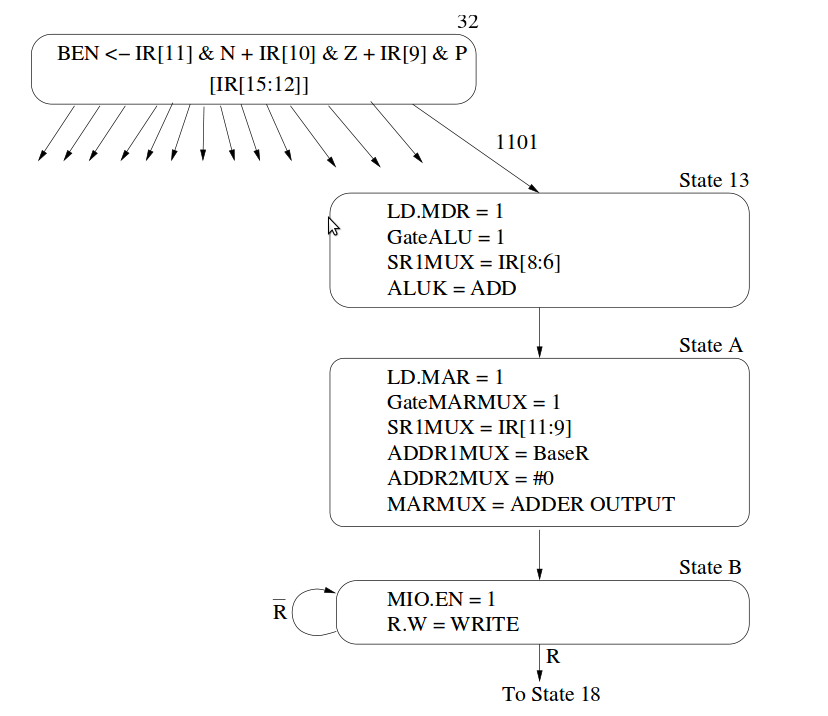
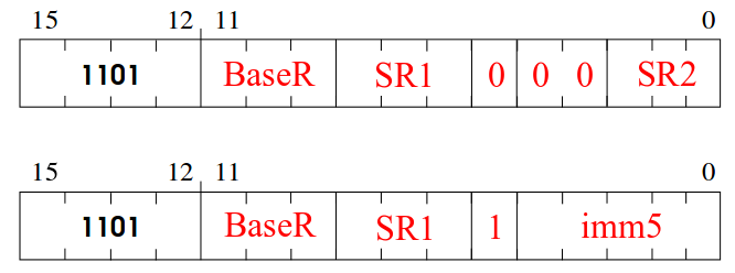
- What does this new instruction do? Adds contents of SR1 (IR[8:6]) to SR2 (or immediate) and store the result in location specified by BaseR (IR[11:9]).
- There are two different formats for specifying the operands of this instruction. Fill them out below.