- Assume that there are about 400 students in your class. If every student is to be assigned a unique bit pattern, what is the minimum number of bits required to do this?
- How many more students can be admitted to the class without requiring additional bits for each student's unique bit pattern?
Without changing their values, convert the following 2's complement binary numbers into 8-bit 2's complement numbers.
- 010110
- 1101
- 1111111000
- 01
Compute the following. Assume each operand is a 2's complement binary number.
- 01 + 1011
- 11 + 01010101
- 0101 + 110
- 01 + 10
Express the value 0.3 in the 32-bit floating point format that we discussed in class today. Feel free to only show fraction bits [22:15], rather than all the fraction bits, [22:0]. Notation: The symbol [22:15] signifies all 8 bits from bit 22 to bit 15.
Convert the following floating point representation to its
decimal equivalent:
1 10000010 10101001100000000000000
Perform the following logical operations. Express your answers in hexadecimal notation.
- xABCD OR x9876
- x1234 XOR x1234
- xFEED AND (NOT(xBEEF))
Fill in the truth table for the equations given. The first line is done as an example.
Q2 = NOT ((Y OR Z) AND (X AND Y AND Z))
X Y Z |
Q1 Q2 |
|---|---|
0 0 0 |
0 1 |
|
|
|
|
|
|
|
|
|
|
|
|
|
|
|
|
|
|
|
|
|
A<=Has Professor Patt been uncomfortably warm this summer?
B<=Does Professor Patt want a new, fresher look?
C<=Are beards cool?
We think that Professor Patt should shave his beard if he has been uncomfortably warm this summer. He should also shave his beard if he wants a new fresher look and beards are not cool.
Write the logic equation for Y in terms of A,B,C that solves this problem, and draw the gate-level diagram.
- (3.11) Draw a transistor-level diagram for a three-input AND gate and a three-input OR gate. Do this by extending the designs from Figures 3.6a and 3.7a. (Figures can be found in the book on pages 56 & 57 respectively).
- Replace the transistors in your diagrams from part (a)
with either a wire or no wire to reflect the circuit’s operation when
the following inputs are applied:
-
A = 1, B = 0, C = 0
- The transistor circuit shown below produces the accompanying truth table. The inputs to some of the gates of the transistors are not specified. Also, the outputs for some of the input combinations of the truth table are not specified. Complete both specifications. i.e., all transistors will have their gates properly labeled with either A, B, or C,
and all rows of the truth table will have a 0 or 1 specified as the output.
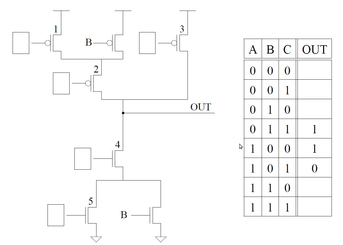
Figure 1
For example, in part a, the missing item is X. That is 0 OR 0 = 0 and 0 OR 1 = 1.
- 0 OR X = ___
- 1 OR X = ___
- 0 AND X = ___
- 1 AND X = ___
- __ XOR X = X